Change to read:
METERED-DOSE INHALERS AND DRY POWDER INHALERS
The following tests are applicable to metered-dose inhalers that are formulated as suspensions or solutions of active drug in propellants and dry powder inhalers presented as single or multidose units.The following test methods are specific to the aforementioned inhalers and may require modification when testing alternative inhalation technologies (for example,breath-actuated metered-dose inhalers,or dose-metering nebulizers).However,Pharmacopeial requirements for all dose-metering inhalation dosage forms require determination of the delivered dose and Aerodynamic Size Distribution.In all cases,and for all tests,prepare and test the inhaler as directed on the label and the instructions for use.When these directions are not provided by the product manufacturer,follow the precise dose discharge directions included in the tests below.
Delivered-Dose Uniformity
Unless otherwise directed in the individual monograph,the drug content of the minimum delivered dose from each of 10separate containers is determined in accordance with the procedure described below.
Unless otherwise specified in the individual monograph,the requirements for dosage uniformity are met if not less than 9of the 10doses are between 75%and 125%of the specified target-delivered dose and none is outside the range of 65%to 135%of the specified target-delivered dose.If the contents of not more than 3doses are outside the range of 75%to 125%of the specified target-delivered dose,but within the range of 65%to 135%of the specified target-delivered dose,select 20additional containers,and follow the prescribed procedure for analyzing 1minimum dose from each.The requirements are met if not more than 3results,out of the 30values,lie outside the range of 75%to 125%of the specified target-delivered dose,and none is outside the range of 65%to 135%of the specified target-delivered dose. USP28
USP28
SAMPLING THE DELIVERED DOSE FROM METERED-DOSE INHALERS
To determine the content of active ingredient in the discharged spray from a metered-dose inhaler,use the sampling apparatus described below,using a flow rate of 28.3Lof air per minute (±5%),unless otherwise stated in the individual monograph.
Apparatus A—
The apparatus (see Figure 1)
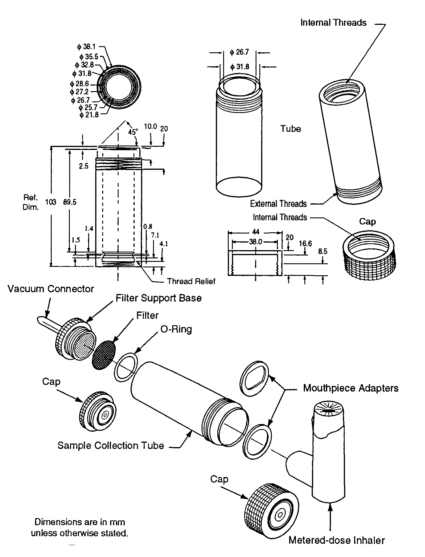 consists of a filter support base with an open-mesh filter support,such as a stainless steel screen,a collection tube that is clamped or screwed to the filter support base,and a mouthpiece adapter to ensure an airtight seal between the collection tube and the mouthpiece.Use a mouthpiece adapter that ensures that the tip of the inhaler mouthpiece is flush with the open end of the sample collection tube.The vacuum connector is connected to a system comprising a vacuum source,flow regulator,and flowmeter.The source should be capable of pulling air through the complete assembly,including the filter and the inhaler to be tested,at the desired flow rate.When testing metered-dose inhalers,air should be drawn continuously through the system to avoid loss of drug into the atmosphere.The filter support base is designed to accommodate 25-mm diameter filter disks.At the airflow being used,the sample collection tube and the filter disk must be capable of quantitatively collecting the delivered dose.The filter disk and other materials used in the construction of the apparatus must be compatible with the drug and the solvents that are used to extract the drug from the filter.One end of the collection tube is designed to hold the filter disk tightly against the filter support base.When assembled,the joints between the components of the apparatus are airtight so that when a vacuum is applied to the base of the filter,all of the air drawn through the collection device passes through the inhaler.
;)
Fig.1.Sampling apparatus for pressurized metered-dose inhalers.
Procedure—
Prepare the inhaler for use according to the label instructions.Unless otherwise specified in the individual monograph,with the vacuum pump running,ensuring an airflow rate through the inhaler of 28.3Lof air per minute (±5%),discharge the minimum recommended dose into the apparatus through the mouthpiece adapter by depressing the valve for a duration sufficient to ensure that the dose has been completely discharged.Detach the inhaler from Apparatus A,and disconnect the vacuum.Assay the contents of the apparatus for drug after rinsing the filter and the interior of the apparatus with a suitable solvent.
SAMPLING THE DELIVERED DOSE FROM DRY POWDER INHALERS
To determine the content of active ingredient emitted from the mouthpiece of a dry powder inhaler,use Apparatus B(see Figure 2).This apparatus is capable of sampling the emitted doses at a variety of airflow rates.
;)
Fig.2.Apparatus B:Sampling apparatus for dry powder inhalers.(See Table 1for component specifications.)
Apparatus B—
The apparatus is similar to that described in Figure 1for testing metered-dose inhalers.In this case,however,the filter and collection tube have a larger internal diameter to accommodate 47-mm diameter filter disks.This feature enables dosage collection at higher airflow rates—up to 100Lof air per minute—when necessary.Amouthpiece adapter ensures an airtight seal between the collection tube and the mouthpiece of the dry powder inhaler being tested.The mouthpiece adapter must ensure that the tip of the inhaler mouthpiece is flush with the open end of the sample collection tube.Tubing connectors,if they are used,should have an internal diameter greater than or equal to 8mm to preclude their own internal diameters from creating significant airflow resistance.Avacuum pump with excess capacity must be selected in order to draw air,at the designated volumetric flow rate,through both the sampling apparatus and the inhaler simultaneously.Atimer-controlled,low resistance,solenoid-operated,two-way valve is interposed between the vacuum pump and the flow-control valve to control the duration of flow.This type of valve enables 4.0Lof air (±5%)to be withdrawn from the mouthpiece of the inhaler at the designated flow rate.Flow control is achieved by ensuring that critical (sonic)flow occurs in the flow-control valve (absolute pressure ratio P3/P2£0.5under conditions of steady-state flow).
Procedure—
Operate the apparatus at an airflow rate USP28that produces a pressure drop of 4kPa (40.8cm H2O)over the inhaler to be tested and at a duration USP28consistent with the withdrawal of 4Lof air from the mouthpiece of the inhaler.[NOTE—If the flow rate and duration are defined otherwise in the monograph,adjust the system to within 5%of those values.]Determine the test flow rateUSP28using Apparatus Bas follows.Insert an inhaler into the mouthpiece adapter to ensure an airtight seal.In cases where the drug packaging modifies the inhaler's resistance to airflow,use a loaded,drug-free inhaler (with previously emptied packaging).In other cases,use an unloaded (drug free)inhaler.Connect one port of a differential pressure transducer to the pressure tap,P1,and leave the other open to the atmosphere.Switch on the pump,and open the two-way solenoid valve.Adjust the flow-control valve until the pressure drop across the inhaler is 4.0kPa (40.8cm H2O).Ensure that critical (sonic)flow occurs in the flow-control valve by determining the individual values for absolute pressure,P2and P3,so that their ratio P3/P2is less than or equal to 0.5.If this criterion cannot be achieved,it is likely that the vacuum pump is worn or of insufficient capacity.Critical (sonic)flow conditions in the flow-control valve are required in order to ensure that the volumetric airflow drawn from the mouthpiece is unaffected by pump fluctuations and changes in airflow resistance of the inhaler.USP28Remove the inhaler from the mouthpiece adapter and without disturbing the flow-control valve,measure the airflow rate drawn from the mouthpiece,Qout,by connecting a flowmeter to the mouthpiece adaptor in an airtight fashion.Use a flowmeterUSP28calibrated for the volumetric flow leaving the meter to directly determine Qoutor,if such a meter is unobtainable,calculate the volumetric flow leaving the meter (Qout)using the ideal gas law.For example,for a meter calibrated for the entering volumetric flow (Qin),use the formula:
USP28If the flow rate is greater than 100Lof air per minute,adjust the flow-control valve until QoutUSP28equals 100Lper minute;otherwise,record the value of Qout,USP28and leave the flow-control valve undisturbed.Define the test flow duration,T=240/Qout,USP28in seconds,so that a volume of 4.0Lof air (±5%)is withdrawn from the inhaler at the test flow rate Qout,USP28and adjust the timer controlling the operation of the two-way solenoid valve accordingly.Prime or load the inhaler with powder for inhalation according to the labeled instructions.With the vacuum pump running and the solenoid valve closed,insert the inhaler mouthpiece horizontally into the mouthpiece adapter.Discharge the powder into the sampling apparatus by activating the timer controlling the solenoid valve and withdrawing 4.0Lof air from the inhaler at the previously defined airflow rate.If the labeled instructions so direct,repeat the operation so as to simulate the use of the inhaler by the patient (e.g.,inhale two or three times,if necessary,to empty the capsule).Repeat the whole operation n-1times beginning with the text,“Prime or load the inhaler with powder,”where nis the number of times defined in the labeling as the minimum recommended dose.Detach the dry powder inhaler from the sampling apparatus,and disconnect the vacuum tubing,D.Assay the contents of the apparatus for drug after rinsing the filter and the interior of the apparatus with a suitable solvent.Where specified in individual monographs,perform this test under conditions of controlled temperature and humidity.
Qout=QinP0/(P0–DP),
where P0is the atmospheric pressure and DPis the pressure drop over the meter.
Table 1.Component Specifications for Apparatus B(see Figure 2)
| Code | Item | Description | Dimensions |
| A | Sample collection tubea | See Fig.2 | 34.85-mm ID×12-cm length |
| B | Filterb | See Fig.2 | 47-mm glass fiber filter |
| C | Connector | (e.g.,short metal coupling with low diameter branch to P3) |
³8-mm ID |
| D | Vacuum tubing | (e.g.,silicon tubing with an outside diameter of 14 mm and an internal diameter of 8mm) |
8±0.5-mm ID×50±10-cm length |
| E | Two-way solenoid valvec | See Fig.2 | Minimum airflow orifice having an internal diameter of ³8mm and a maximum response time of 100milliseconds |
| F | Vacuum pumpd | See Fig.2 | Pump must be capable of drawing the required flow rate through the assembled apparatus with the dry powder inhaler in the mouthpiece adapter.Connect the pump to the solenoid valve using short and wide (³10-mm ID)vacuum tubing and connectors to minimize pump capacity requirements. |
| G | Timere | See Fig.2 | The timer switches current directly to the solenoid valve for the required duration. |
| P1 | pressure tap | See Fig.2 | 2.2-mm ID,3.1-mm ODflush with the internal surface of the sample collection tube, centered and burr free,59.0mm from its inlet |
| P1,P2,P3 | pressure measurementsf |
||
| H | Flow-control valveg |
See Fig.2 | Adjustable regulating valve with maximum Cv³1h |
|
a
An example being a Millipore product number XX4004700(Millipore Corporation,80,Ashby Road,Bedford,MA01732),modified so that the exit tube has an ID³8-mm,fitted with Gelman product number 61631.
|
|||
|
b
A/E(Gelman Sciences Inc.,600South Wagner Road,Ann Arbor,MI48106)or equivalent.
|
|||
|
c
ASCOproduct number 8030G13,Automatic Switch Company,60Hanover Road,Florham Park,NJ07932.
|
|||
|
d
Gast product type 1023,1423,or 2565(Gast Manufacturing Inc.,PO Box 97,Benton Harbor,MI49022)or equivalent.
|
|||
|
e
Eaton Product number 45610-400(Eaton Corporation,Automotive Products Division,901,South 12th Street,Watertown,WI53094)or equivalent.
|
|||
|
f
An example being a PDM210pressure meter (Air-Neotronics Ltd.,Neotronics Technology plc,Parsonage Road,Takeley,Bishop's Stortford,CM226PU,UK),or equivalent.
|
|||
|
g
Parker Hannifin type 8FV12LNSS(Parker Hannifin plc.,Riverside Road,Barnstable,Devon EX311NP,UK)or equivalent.
|
|||
|
h
Flow Coefficient,as defined by ISA S75.02“Control valve capacity test procedure”in Standards and Recommended Practices for Instrumentation and Control,10th ed.,Vol.2,1989.Published by Instrument Society of America,67Alexander Drive,P.O.Box 1227,Research Triangle Park,NC27709,U.S.A.
|
Delivered-Dose Uniformity over the Entire Contents
The test forDelivered-Dose Uniformity over the Entire Contents is required for inhalers (e.g.,metered-dose inhalers or dry powder inhalers)containing multiple doses of drug formulation (e.g.,solution,suspension,or dry powder)either in reservoirs or in premetered dosage units (e.g.,blisters),and for drug formulations packaged in reservoirs or in multiple-dose assemblies of premetered dosage units that have a predetermined dose sequence,where these multiple-dose assemblies are labeled for use with a named inhalation device.The test for Delivered-Dose Uniformity over the Entire Contentsalso ensures that multidose products supply the total number of discharges stated on the label.Unless otherwise directed in the individual monograph,the drug content of at least 9of the 10doses collected from one inhaler,in accordance with the procedure below,are between 75%and 125%of the target-delivered dose,USP28and none is outside the range of 65%to 135%of the target-delivered dose.USP28If the contents of not more than 3doses are outside the range of 75%to 125%,but within the range of 65%to 135%of the target-delivered dose,USP28select 2additional inhalers,and follow the prescribed procedure for analyzing 10doses from each.The requirements are met if not more than 3results,out of the 30values,lie outside the range of 75%to 125%of the target-delivered dose,USP28and none is outside the range of 65%to 135%of the target-delivered dose.USP28
METERED-DOSE INHALERS
Apparatus—
Use Apparatus Aas directed in Sampling the Delivered-Dose from Metered-Dose Inhalers under Delivered-Dose Uniformity at a flow rate of 28.3Lof air per minute (±5%).
Procedure—
Asingle dose is defined as the number of sprays specified in the product labeling as the minimum recommended dose.Select a single metered-dose inhaler,and follow the labeled instructions for priming,shaking,cleaning,and firing the inhaler throughout.Unless otherwise prescribed in the patient instructions,shake the inhaler for 5seconds,and fire one minimum recommended dose to waste.Wait for 5seconds,and collect the next dose.Detach the inhaler from Apparatus A,and disconnect the vacuum.Assay the contents of the apparatus for drug after rinsing the filter and the interior of the apparatus with a suitable solvent.Collect two more doses,allowing at least 5seconds between doses.Discharge the device to waste,waiting for not less than 5seconds between actuations (unless otherwise specified in the individual monograph),until (n/2)+1minimum recommended doses remain,in which nis the number of minimum recommended doses on the label.Collect four more doses,allowing at least 5seconds between doses,unless otherwise specified in the individual monograph.Discharge the device to waste,as before,until three doses remain.Collect the final three doses,allowing at least 5seconds between doses.Note that the rate of discharges to waste should not be such to cause excessive canister cooling.
DRY POWDER INHALERS
Apparatus—
Use Apparatus Bas directed in Sampling the Delivered Dose from Dry Powder Inhalersunder Delivered-Dose Uniformity at the appropriate airflow rate for testing.
Procedure—
Proceed as directed for Procedurein Sampling the Delivered Dose from Dry Powder Inhalersunder Delivered-Dose Uniformity.Asingle dose is defined as the number of actuations stated in the product labeling as the minimum recommended dose.Select a single inhaler and follow the labeled instructions for loading with powder,discharging and cleaning throughout.Collect a total of 10doses—three doses at the beginning,four in the middle [(n/2)-1to (n/2)+2,where nis the number of minimum recommended doses on the label],and three at the end—of the labeled contents following the labeled instructions.Prior to collecting each of the doses to be analyzed,clean the inhaler as directed in the labeling.
Particle Size
The particle or droplet size distribution in the spray discharged from metered-dose inhalers,and the particle size distribution in the cloud discharged from dry powder inhalers,are important characteristics used in judging inhaler performance.While particle size measurement by microscopy can be used to evaluate the number of large particles,agglomerates,and foreign particulates in the emissions of metered-dose inhalers (e.g.,Epinephrine Bitartrate Inhalation Aerosol),whenever possible this test should be replaced with a method to determine the aerodynamic size distribution of the drug aerosol leaving the inhaler.The aerodynamic size distribution defines the manner in which an aerosol deposits during inhalation.When there is a log-normal distribution,the aerodynamic size distribution may be characterized by the mass median aerodynamic diameter (MMAD)and geometric standard deviation (GSD).The aerodynamic size distribution of the drug leaving metered-dose and dry powder inhalers is determined using Apparatus 1,2,3,4,5,or 6USP28as specified in this chapter.Afine particle dose or fine particle fraction can also be determined as that portion of the inhaler output having an aerodynamic diameter less than the size defined in the individual monograph.This may be expected to correlate with the drug dose or that fraction of the drug dose that penetrates the lung during inhalation.Individual monographs may also define the emitted fractions of the delivered dose in more than one aerodynamic size range.
AERODYNAMIC SIZE DISTRIBUTION
Cascade impaction devices classify aerosol particles and droplets on the basis of those particles'aerodynamic diameters.The principle of their operation,whereby they separate aerosol particles and droplets from a moving airstream on the basis of particle or droplet inertia,is shown in Figure 3.
;)
Fig.3.Schematic representation of the principle of operation of cascade impactors.(Asingle jet per impactor stage is shown.Impactors with multiple jets in each stage function in the same manner.)
Because the dimensions of the induction port used to connect inhalers to the cascade impactors and impingers (shown in Apparatus 1,2,3,4,5,and 6)USP28also define the mass of drug that enters the aerodynamic sizing device,these are carefully defined and,where possible,are held constant between each apparatus (see Figures 4,6,7,8,and 9).USP28
;)
Fig.4.Apparatus 1:Assembly of induction port and entrance cone mounted on cascade impactor.
;)
Fig.4a.Apparatus 1:Expanded view of induction port for use with metered-dose and dry powder inhalers.
;)
Fig.4b.Apparatus 1:Expanded view of the entrance cone for mounting induction port on the Andersen cascade impactor without preseparator.
;)
Fig.5.Apparatus 2,3,and 4:General control equipment.(See Table 2for component specifications.)
;)
Fig.6.Apparatus 2:Assembly of induction port,stage collector,and filter holder.(Marple-Miller impactor,Model 160with USPinduction port.)
;)
Fig.7.Apparatus 3:Expanded views of top for the Andersen preseparator adapted to the USPinduction port.
;)
Fig.8.Apparatus 4:Schematic of multistage liquid impinger.(See Table 3for component specifications.)
Because the size distributions produced by different impactors are often a function of impactor design and the airflow rate through them,there is a need to standardize the instruments that are used to test inhalers (i.e.,Apparatus 1or 6for metered-dose inhalers)USP28or to provide guidelines on system suitability where different apparatuses may be used (i.e.,Apparatus 2,3,4,or 5for dry powder inhalers).USP28
Because of the varied nature of the formulations and devices being tested,the cascade impaction system and technique selected for testing an inhaler should fulfill a number of criteria.
Stage Mensuration—
Manufacturers of cascade impaction devices provide a definitive calibration for the separation characteristics of each impaction stage in terms of the relationship between the stage collection efficiency and the aerodynamic diameter of particles and droplets passing through it as an aerosol.Calibration is a property of the jet dimensions,the spatial arrangement of the jet and its collection surface,and the airflow rate passing through it.Because jets can corrode and wear over time,the critical dimensions of each stage,which define that impaction stage's calibration,must be measured on a regular basis.This process,known as stage mensuration,replaces the need for repetitive calibration (using standard aerosols)and ensures that only devices that conform to specifications are used for testing inhaler output.The process involves the measurement and adjustment of the critical dimensions of the instrument.
Interstage Drug Loss(wall losses)—
Where method variations are possible and there is no apparatus specified in the monograph,the selected technique should ensure that not more than 5%of the inhaler's total delivered drug mass (into the impactor)is subject to loss between the impaction device's sample collection surfaces.In the event that interstage drug losses are known to be greater than 5%,either the procedure should be performed in such a way that wall losses are included along with the associated collection plate,or an alternative apparatus should be used.As an example,the following procedures described for Apparatus 1and 3have been written to include wall losses along with the associated collection plate.Provided,however,that such losses are known to be less than or equal to 5%of the total delivered drug mass into the impactor and that there are no instructions to the contrary in an individual monograph,the technique may be simplified by only assaying drug on the collection plates.
Re-Entrainment—
Where method variations are possible,the selected technique should seek to minimize particle re-entrainment (from an upper to a lower impaction stage)on stages that contribute to size fractions defined in the individual monograph,especially where this may affect the amounts of drug collected.Minimizing the number of sampled doses,the use of coated particle collection surfaces,and proving that multiple-dose techniques produce statistically similar results to those from smaller numbers of doses,are all methods that can be used for this purpose.In the event that re-entrainment cannot be avoided,the number of doses collected,the time interval between doses,and the total duration of airflow through the cascade impaction device should be standardized.Under these circumstances,the presentation of impaction data should not presume the validity of the impactor's calibration (i.e.,aerodynamic diameter ranges should not be assigned to drug masses collected on specific stages).
By using appropriate assay methods and a suitable mensurated impaction device,aerodynamic particle size distributions can be determined for drugs leaving the mouthpieces of metered-dose or dry powder inhalers.If temperature or humidity limits for use of the inhaler are stated on the label,it may be necessary to control the temperature and humidity of the air surrounding and passing through the device to conform to those limits.Ambient conditions are presumed,unless otherwise specified in individual monographs.
Mass Balance—
In addition to the size distribution,good analytical practice dictates that a mass-balance be performed in order to confirm that the amount of the drug discharged from the inhaler,which is captured and measured in the induction port-cascade impactor apparatus,is within an acceptable range around the expected value.USP28The total mass of drug collected in all of the components (material balance)divided by the total number of minimum recommended doses discharged is not less than 75%and not more than 125%of the average minimum recommended dose determined during testing for Delivered-Dose Uniformity.This is not a test of the inhaler but serves to ensure that the test results are valid.
Use one of the multistage impaction devices shown below,or an equivalent,to determine aerodynamic particle size distributions of drugs leaving the mouthpieces of metered-dose or dry powder inhalers.Apparatus 1and 6[Figures 4and 9(without preseparator),respectively]areUSP28intended for use with metered-dose inhalers at a single airflow rate.Apparatus 2,3,4,and 5(Figures 6,7,8,and 9,respectively)USP28are intended for use with dry powder inhalers at the appropriate airflow rate,Qout,determined earlier,provided that the value of QoutUSP28falls in the range 30–100Lper minute.
NOTE—If Qoutis greater than 100Lper minute,testing should be performed with Qoutset at 100Lper minute;if Qoutis less than 30Lper minute,testing is performed with Qoutat 30Lper minute.
USP28
Apparatus 1for Metered-Dose Inhalers—
Use this apparatus,or an equivalent,at a flow rate of 28.3Lper minute (±5%),as specified by the manufacturer of the cascade impactor.
Design—
The design and assembly of this apparatus and the induction port to connect the device to an inhaler are shown in Figures 4,4a,and 4b1.
Procedure—
Set up the multistage cascade impactor as described in the manufacturer's literature with an after filter below the final stage to capture any fine particles that otherwise would escape from the device.To ensure efficient particle capture,coat the particle collection surface of each stage with glycerol,silicone oil,or other suitable liquid typically deposited from a volatile solvent,unless it has been demonstrated to be unnecessary.USP28Attach the induction port and mouthpiece adapter to produce an airtight seal between the inhaler mouthpiece and the induction port as shown in Figure 4.Use a mouthpiece adapter that ensures that the tip of the inhaler mouthpiece is flush with the open end of the induction port.Ensure that the various stages of the cascade impactor are connected with airtight seals to prevent leaks.Turn on the vacuum pump to draw air through the cascade impactor,and calibrate the airflow through the system with an appropriate flowmeter attached to the open end of the induction port.Adjust the flow-control valve on the vacuum pump to achieve steady flow through the system at the required rate,and ensure that the airflow through the system is within ±5%of the flow rate specified by the manufacturer.Unless otherwise prescribed in the patient instructions,shake the inhaler for 5seconds and discharge one delivery to waste.With the vacuum pump running,insert the mouthpiece into the mouthpiece adapter and immediately fire the minimum recommended dose into the cascade impactor.Keep the valve depressed for a duration sufficient to ensure that the dose has been completely discharged.If additional sprays are required for the sample,wait for 5seconds before removing the inhaler from the mouthpiece adapter,shake the inhaler,reinsert it into the mouthpiece adapter,and immediately fire the next minimum recommended dose.Repeat until the required number of doses have been discharged.The number of minimum recommended doses discharged must be sufficient to ensure an accurate and precise determination of Aerodynamic Size Distribution.[NOTE—The number of minimum recommended doses is typically not greater than 10.]After the last dose has been discharged,remove the inhaler from the mouthpiece adapter.Rinse the mouthpiece adapter and induction port with a suitable solvent,and dilute quantitatively to an appropriate volume.Disassemble the cascade impactor,place each stage and its associated collection plate or filter in a separate container,and rinse the drug from each of them.[NOTE—If it has been determined that wall losses in the impactor are less than or equal to 5%,then the collection plates only may be used.]Dilute each quantitatively to an appropriate volume.Using the method of analysis specified in the individual monograph,determine the mass of drug collected in each of the components.To analyze the data,proceed as directed under Data Analysis.
Apparatus 2for Dry Powder Inhalers—
Design—
The design and assembly of Apparatus 2,and the induction port to connect the device to an inhaler,are shown inFigure 6.2[NOTE—The induction port is shown in detail in Figure 4a.]The impactor has five impaction stages and an after filter.At a volumetric airflow rate of 60Lper minute (the nominal flow rate,Qn),the cutoff aerodynamic diameters D50,Qnof Stages 1to 5are 10,5,2.5,1.25,and 0.625µm,respectively.The after filter effectively retains aerosolized drug in the particle size range up to 0.625µm.Set up the multistage cascade impactor with the control system as specified in Figure 5.To ensure efficient particle capture,coat the particle collection surface of each stage with glycerol,silicone oil,or other suitable liquid typically deposited from a volatile solvent,unless it has been demonstrated to be unnecessary.USP28Assemble the impactor as described in the manufacturer's literature with an after filter below the final stage to capture any fine particles that otherwise would escape from the device.Attach the induction port and mouthpiece adapter to produce an airtight seal between the inhaler mouthpiece and the induction port.Use a mouthpiece adapter that ensures that the tip of the inhaler mouthpiece is flush with the open end of the induction port.Ensure that the various stages of the cascade impactor are connected with airtight seals to prevent leaks.
Turn on the vacuum pump,open the solenoid valve,and calibrate the airflow through the system as follows.Connect a flowmeter to the induction port.Use a flowmeter calibrated for the volumetric flow leaving the meter to directly determine Qout,or,if such a meter is unobtainable,calculate the volumetric flow leaving the meter (Qout)using the ideal gas law.For example,for a meter calibrated for the entering volumetric flow (Qin),use the formula:
Qout=QinP0/(P0–DP),
where P0is the atmospheric pressure and DPis the pressure drop over the meter.USP28Adjust the flow-control valve to achieve a steady flow through the system at the required rate,Qout,so that QoutUSP28is within ±5%of the value determined during testing for Delivered-Dose Uniformity.Ensure that critical flow occurs in the flow-control valve,at the airflow rate to be used during testing,byUSP28using the following procedure.With the inhaler in place,and the intended flow running,measure the absolute pressure on both sides of the flow-control valve (P2and P3in Figure 5).Aratio of P3/P2£0.5indicates critical flow.Switch to a more powerful pump,and remeasure the test flow rate if P3/P2>0.5.Adjust the timer controlling the operation of the two-way solenoid valve so that it opens this valve for a duration of Tseconds as determined during testing for Delivered-Dose Uniformity.USP28Prime or load the dry powder inhaler with powder for inhalation according to the labeled instructions.With the vacuum pump running and the two-way solenoid valve closed,insert the inhaler mouthpiece,held horizontally,into the induction port mouthpiece adapter.Discharge the powder into the apparatus by opening the two-way solenoid valve for a duration of Tseconds.After the two-way solenoid valve has closed,remove the inhaler from the mouthpiece adapter.If additional doses are required for the sample,reload the inhaler according to the labeled instructions,reinsert the mouthpiece into the mouthpiece adapter,and repeat the operation until the required number of doses have been discharged.After discharge of the last dose,switch off the vacuum pump.
Rinse the mouthpiece adapter and induction port with a suitable solvent,and quantitatively dilute to an appropriate volume.Disassemble the cascade impactor,and place the after filter in a separate container.Rinse the drug from each of the stages and the filter,and quantitatively dilute each to an appropriate volume.Using the method of analysis specified in the individual monograph,determine the mass of drug collected in each of the components.Determine the cutoff diameters of each of the individual stages of the impactor,at the value of Q=QoutUSP28employed in the test by the formula:
D50,Q=D50,Qn(Qn/Q)1/2,(Eq.1)
where D50,Qis the cutoff diameter at the flow rate,Q,employed in the test,and the subscript,n,refers to the nominal values determined when Qnequals 60Lper minute.Thus,when Qequals 40Lper minute,the cutoff diameter of Stage 2is given by the formula:
D50,40LPM=5µm ×[60/40]1/2=6.1µm.
General Procedure—
Perform the test using Apparatus 2at the airflow rate,QoutUSP28determined earlier,during testing for Delivered-Dose Uniformity,provided QoutUSP28is less than or equal to 100Lper minute.[NOTE—If QoutUSP28is greater than 100Lper minute,use an airflow rate of 100Lper minute.]Connect the apparatus to a flow control system that is based upon critical (sonic)flow as specified in Figure 5(see also Table 2).
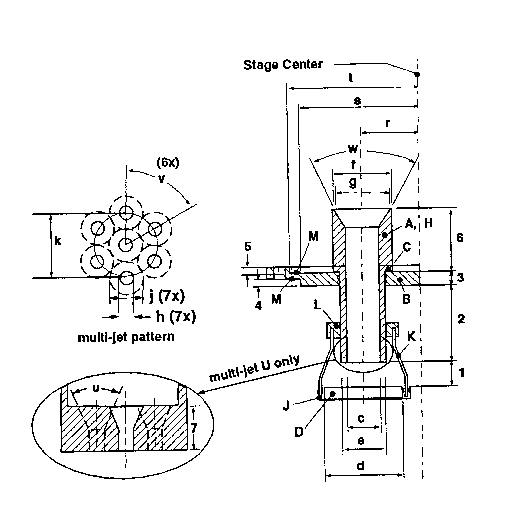
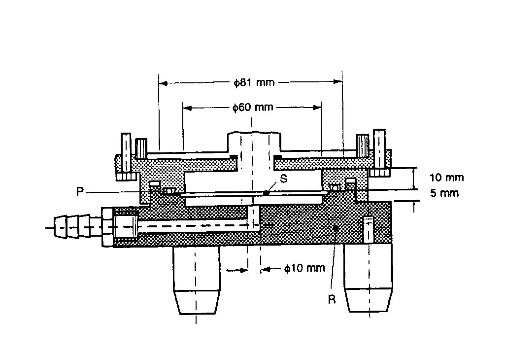
Table 2.Component Specifications for Figure 5
| Code | Item | Description | Dimensions |
| A | Connector | (e.g.,short metal coupling with low diameter branch to P3) |
³8-mm ID |
| B | Vacuum tubing | (e.g.,silicon tubing with an outside diameter of 14mm and an internal diameter of 8mm) |
8±0.5-mm ID×50±10-cm length |
| C | Two-way solenoid valvea | See Figure 5 | Internal diameter orifice of 9.5mm and a Cv=1.8a,minimal resistance to airflow and a response time <100milliseconds. |
| D | Vacuum pumpb | See Figure 5 | Pump must be capable of drawing the required flow rate through the assembled apparatus with the dry powder inhaler in the mouthpiece adapter. Connect the pump to the solenoid valve using short and wide (³10-mm ID)vacuum tubing and connectors to minimize pump capacity requirements. |
| E | Timerc | See Figure 5 | The timer switches current directly to the solenoid valve for the required duration. |
| P2,P3 | pressure measurements | Determine under steady-state flow conditions with an absolute pressure transducer. |
|
| F | Flow control valved | See Figure 5 | Adjustable regulating valve with maximum Cv³1. |
|
a
An example being ASCOproduct number 8030G13(Automatic Switch Company,60Hanover Road,Florham Park,NJ07932)or equivalent.See also Footnote hin Table 1.
|
|||
|
b
Gast product type 1023,1423,or 2565(Gast Manufacturing Inc.,PO Box 97,Benton Harbor,MI49022)or equivalent.
|
|||
|
c
An example being Eaton Product number 45610-400(Eaton Corporation,Automotive Products Division,901South 12th Street,Watertown,WI53094)or equivalent.
|
|||
|
d
Parker Hannifin type 8FV12LNSS,or equivalent (Parker Hannifin plc,Riverside Road,Barnstable,Devon EX311NP,UK).See also Footnote hin Table 1.
|
Table 3.Component Units of Multistage Liquid Impinger (see Figure 8)
| Code1 | Item | Description | Dimensions2 |
| A,H | Jet tube | Metal tube screwed onto partition wall sealed by gasket (C), polished inner surface |
see Figure 8a |
| B,G | Partition wall | Circular metal plate,diameter | 120 |
| Thickness | see Figure 8a | ||
| C | Gasket | e.g.,PTFE | to fit jet tube |
| D | Impaction plate | Porosity Osintered-glass disk, | see Figure 8a |
| Diameter | |||
| E | Glass cylinder | Plane polished cut glass tube | |
| Height,including gaskets | 46 | ||
| Outer diameter | 100 | ||
| Wall thickness | 3.5 | ||
| Sampling port (F)diameter | 18 | ||
| Stopper in sampling port | ISO24/25 | ||
| J | Metal frame | L-profiled circular frame with slit | to fit impaction plate |
| Inner diameter | |||
| Height | 4 | ||
| Thickness of horizontal section | 0.5 | ||
| Thickness of vertical section | 2 | ||
| K | Wire | Steel wire interconnecting metal frame and sleeve (two for each frame) Diameter |
1 |
| L | Sleeve | Metal sleeve secured on jet tube by screw |
to fit jet tube |
| Inner diameter | |||
| Height | 6 | ||
| Thickness | 5 | ||
| M | Gasket | e.g.,silicone | to fit glass cylinder |
| N | Bolt | Metal bolt with nut (six pairs),length | 205 |
| Diameter | 4 | ||
| P | O-ring | Rubber O-ring,diameter ×thickness | 66.34×2.62 |
| Q | O-ring | Rubber O-ring,diameter ×thickness | 29.1×1.6 |
| R | Filter holder | Metal housing with stand and outlet | see Figure 8b |
| S | Filter support | Perforated sheet metal,diameter Hole diameter Distance between holes (center-points) |
65 3 4 |
| T | Snap-locks | ||
| U | Multi-jet tube | Jet tube (H)ending in multijet arrangement |
see inserts Figure 8a |
| V | Outlet | Outlet and nozzle for connection to vacuum |
Internal diameter ³10(Figure 8b) |
|
1
See Fig.8.
|
|||
|
2
Measurements in mm unless otherwise stated.
|
;)
Fig.8a.Apparatus 4:Details of jet tube and impaction plate.Inserts show end of multi-jet tube Uleading to Stage 4.(See Table 4for dimension specifications.)
;)
Fig.8b.Apparatus 4:Expanded view of Stage 5.(See Table 3for component specifications.)
| Type | Code2 | Stage 1 | Stage 2 | Stage 3 | Stage 4 | Filter (Stage 5) |
| Distance | 1 | 9.5(-.0,+.5) | 5.5(-.0,+.5) | 4.0(-.0,+.5) | 6.0(-.0,+.5) | n.a. |
| Distance | 2 | 26 | 31 | 33 | 30.5 | 0 |
| Distance | 3 | 8 | 5 | 5 | 5 | 5 |
| Distance | 4 | 3 | 3 | 3 | 3 | n.a. |
| Distance | 5 | 0 | 3 | 3 | 3 | 3 |
| Distance | 63 | 20 | 25 | 25 | 25 | 25 |
| Distance | 7 | n.a. | n.a. | n.a. | 8.5. | n.a. |
| Diameter | c | 25 | 14 | 8.0(±.1) | 21 | 14 |
| Diameter | d | 50 | 30 | 20 | 30 | n.a. |
| Diameter | e | 27.9 | 16.5 | 10.5 | 23.9 | n.a. |
| Diameter | f | 31.75(-.05,+.00) | 22 | 14 | 31 | 22 |
| Diameter | g | 25.4 | 21 | 13 | 30 | 21 |
| Diameter | h | n.a. | n.a. | n.a. | 2.70(±.05) | n.a. |
| Diameter | j | n.a. | n.a. | n.a. | 6.3 | n.a. |
| Diameter | k | n.a. | n.a. | n.a. | 12.6 | n.a. |
| Radius4 | r | 16 | 22 | 27 | 28.5 | 0 |
| Radius4 | s | 46 | 46 | 46 | 46 | n.a. |
| Radius4 | t | n.a. | 50 | 50 | 50 | 50 |
| Angle | w | 10 |
53 |
53 |
53 |
53 |
| Angle | u | n.a. | n.a. | n.a. | 45 |
n.a. |
| Angle | v | n.a. | n.a. | n.a. | 60 |
n.a. |
|
1
Measurements in mm with tolerances according to ISO2768-m,unless otherwise stated.
|
||||||
|
2
See Figure 8a.
|
||||||
|
3
Including gasket.
|
||||||
|
4
Relative centerline of stage compartment.
|
||||||
|
n.a.:not applicable.
|
||||||
Under steady flow conditions,at the appropriate volumetric airflow rate through the entire apparatus,ensure that critical (sonic)flow occurs in the flow control valve by determining the individual values for absolute pressure,P2and P3,so that their ratio P3/P2is less than or equal to 0.5.CoatUSP28the particle collection surface of each of the stages of the cascade impactor to ensure that particles that have impacted on a given stage are not re-entrained in the flowing airstream,unless this has been shown to be unnecessary.USP28Analyze the data as directed under Data Analysis.
Apparatus 3for Dry Powder Inhalers—
Design—
Apparatus 3is identical to Apparatus 1(Figure 4),except that the manufacturer's preseparator is added atop Stage 0to collect large masses of noninhalable powder prior to their entry into the impactor,and the outlet nipple,used to connect to vacuum tubing B(Figure 5),is replaced with one having an internal diameter ³8mm.To connect the preseparator of the impactor to the induction port (Figure 4a),a specially designed top for the preseparator must be used.This is shown in Figure 7.3The impactor,therefore,has eight stages,a preseparator (to collect large particulates),and an after filter.At a volumetric airflow rate of 28.3Lper minute (the nominal flow rate,Qn),the cutoff aerodynamic diameters D50,Qnof Stages 0to 7are 9.0,5.8,4.7,3.3,2.1,1.1,0.7,and 0.4µm,respectively.The after filter effectively retains aerosolized drug in the particle size range up to 0.4µm.Connect the cascade impactor into the control system specified in Figure 5.Omit Stage 6and Stage 7from the impactor if the test flow rate,Qout,USP28used during testing for Delivered-Dose Uniformity was greater than or equal to 60Lper minute.To ensure efficient particle capture,coat the particle collection surface of each stage with glycerol,silicone oil,or other suitable liquid typically deposited from a volatile solvent,unless it has been demonstrated to be unnecessary.USP28Assemble the impactor as described in the manufacturer's literature with an after filter below the final stage to capture any fine particles that otherwise would escape from the device.Place an appropriate volume (up to 10mL)of an appropriate solvent into the preseparator,or coat the particle collection surfaces of the preseparator to prevent re-entrainment of impacted particles.[Caution—Some solvents form flammable vapor-air mixtures that may be ignited during passage through a vacuum pump.Take appropriate precautions (alternative solvents,use of vapor traps,minimal pump operating times,etc.)to ensure operator safety during testing.
]Attach a molded mouthpiece adapter to the end of the induction port to produce an airtight seal between the inhaler mouthpiece and the induction port.Use a mouthpiece adapter that ensures that the tip of the inhaler mouthpiece is flush with the open end of the induction port.Ensure that the various stages of the cascade impactor are connected with airtight seals to prevent leaks.
Turn on the vacuum pump,open the two-way solenoid valve,and calibrate the airflow through the system as follows.Prime or load the dry powder inhaler with powder for inhalation according to the labeled instructions.With the vacuum pump running and the two-way solenoid valve closed,insert the inhaler mouthpiece,held horizontally,into the induction port mouthpiece adapter.Once the inhaler is positioned,discharge the powder into the apparatus by activating the timer and opening the two-way solenoid valve for the required duration,T±5%,as determined during testing for Delivered-Dose Uniformity.USP28After the two-way solenoid valve has closed,remove the inhaler from the mouthpiece adapter.If additional doses are required for the sample,reload the inhaler according to the labeled instructions,reinsert the mouthpiece into the mouthpiece adapter,and repeat the operation until the required number of doses have been discharged.After discharge of the last dose,remove the inhaler from the mouthpiece adapter,and switch off the vacuum pump.
Carefully disassemble the apparatus.Using a suitable solvent,rinse the drug from the mouthpiece adapter,induction port,and preseparator,and quantitatively dilute to an appropriate volume.Rinse the drug from each stage,and the impaction plate immediately below,into appropriately sized flasks.Quantitatively dilute each flask to an appropriate volume.Using the method of analysis specified in the individual monograph,determine the mass of drug collected in each of the samples.The aerodynamic cutoff diameters of the individual stages of this device,in the airflow range between 30and 100Lper minute,are currently not well established.USP28Do not use the formula in Equation 1to calculate cutoff diameters.
Procedure—
Proceed as directed in the General Procedureunder Apparatus 2,except to use Apparatus 3.
Apparatus 4for Dry Powder Inhalers—
NOTE—Apparatus 4,the multistage liquid impinger,has a small number of stages and is used extensively outside the USA.It is provided here for the benefit of users in countries other than the USA.
USP28
Design—
The design and assembly of Apparatus 4are shown in Figures 8,8a,and 8b.4The induction port,used to connect the device to an inhaler,is shown in Figure 4a.The device is a multi-stage liquid impinger consisting of impaction Stages 1,2,3,and 4and an integral after filter (Stage 5).The collection stages of the liquid impinger (see Figure 8andTable 3)are kept moist,unlike those of traditional impactors,such as Apparatus 1,2,and 3;wetting may produce an effect similar to coating the stages of Apparatus 2and 3at certain flow rates,although this should be confirmed by demonstrating control over re-entrainment as described earlier.An impaction stage comprises an upper horizontal metal partition wall (B)through which a metal inlet jet tube (A)with its impaction plate (D)is protruding;a glass cylinder (E)with sampling port (F),forming the vertical wall of the stage;and a lower horizontal metal partition wall (G)through which a jet tube (H)connects to the lower stage.The tube into Stage 4(U)ends in a multijet arrangement.The impaction plate (D)is secured in a metal frame (J),which is fastened by two wires (K)to a sleeve (L)secured on the jet tube (C).For more detail of the jet tube and impaction plate,see Figure 8a.The horizontal plane of the collection plate is perpendicular to the axis of the jet tube and centrally aligned.The upper surface of the impaction plate is slightly raised above the edge of the metal frame.Arecess around the perimeter of the horizontal partition wall guides the position of the glass cylinder.The glass cylinders are sealed against the horizontal partition walls with gaskets (M)and clamped together by six bolts (N).The sampling ports are sealed by stoppers.The bottom side of the lower partition wall of Stage 4has a concentric protrusion fitted with a rubber O-ring (P)that seals against the edge of a filter placed in the filter holder.The filter holder (R)is a basin with a concentric recess in which a perforated filter support (S)is flush-fitted.The filter holder is designed for 76-mm diameter filters.The whole impaction stage assembly is clamped onto the filter holder by two snap locks (T).The impinger is equipped with an induction port (Figure 4a)that fits onto the Stage 1inlet jet tube.Arubber O-ring on the jet tube provides an airtight connection to the induction port.An elastomeric mouthpiece adapter to fit the inhaler being tested provides an airtight seal between the inhaler and the induction port.
At a volumetric airflow rate of 60Lper minute (the nominal flow rate,Qn),the cutoff aerodynamic diameters D50,Qnof Stages 1to 4are 13.0,6.8,3.1,and 1.7µm,respectively.The after filter effectively retains aerosolized drug in the particle size range up to 1.7µm.Ensure that Apparatus 4is clean and free of drug solution from any previous tests.Place a 76-mm diameter filter in the filter stage,and assemble the apparatus.Use a low pressure filter capable of quantitatively collecting the passing drug aerosol,which also allows a quantitative recovery of the collected drug.Set up Apparatus 4using the control system as specified in Figure 5.Attach the induction port (Figure 4a)and mouthpiece adapter to produce an airtight seal between the inhaler mouthpiece and the induction port.Use a mouthpiece adapter that ensures that the tip of the inhaler mouthpiece is flush with the open end of the induction port.Ensure that the various stages of the apparatus are connected with airtight seals to prevent leaks.Turn on the vacuum pump,open the two-way solenoid valve,and calibrate the airflow through the system as follows.Connect a flowmeter,calibrated for the volumetric flow rate leaving the meter,to the induction port.Adjust the flow-control valve to achieve a steady flow through the system at the required rate,Qout,so that QoutUSP28is within ±5%of the value determined during testing for Delivered-Dose Uniformity.Ensure that critical flow occurs in the flow-control valve,at the value of QoutUSP28to be used during testing,using the following procedure.With the inhaler in place,and the intended flow running,measure the absolute pressure on both sides of the flow-control valve (P2and P3in Figure 5).Aratio of P3/P2£0.5indicates critical flow.Switch to a more powerful pump,and remeasure the test flow rate if P3/P2>0.5.Adjust the timer controlling the operation of the two-way solenoid valve so that it opens that valve for the same duration,T,as used during testing for Delivered-Dose Uniformity.Dispense 20mLof a solvent,capable of dissolving the drug,into each of the four upper stages of Apparatus 4,and replace the stoppers.[Caution—Some solvents form flammable vapor-air mixtures that may be ignited during passage through a vacuum pump.Take appropriate precautions (alternative solvents,use of vapor traps,minimal pump operating times,etc.)to ensure operator safety during testing.
]Tilt the apparatus to wet the stoppers,thereby neutralizing their electrostatic charge.Adjust the timer controlling the operation of the two-way solenoid valve so that it opens the valve for the same duration,T,as used during testing for Delivered-Dose Uniformity.Prime or load the dry powder inhaler with powder for inhalation according to the labeled instructions.With the vacuum pump running and the two-way solenoid valve closed,insert the inhaler mouthpiece,held horizontally,into the induction port mouthpiece adapter.Discharge the powder into the apparatus by activating the timer and opening the two-way solenoid valve for the required duration,T±5%.After the two-way solenoid valve has closed,remove the inhaler from the mouthpiece adapter.If additional doses are required for the sample,reload the inhaler according to the labeled instructions,reinsert the mouthpiece into the mouthpiece adapter,and repeat the operation until the required number of doses have been discharged.After discharge of the last dose,switch off the vacuum pump.
Dismantle the filter stage of Apparatus 4.Carefully remove the filter,and extract the drug with solvent.Rinse the mouthpiece adapter and induction port with a suitable solvent,and quantitatively dilute to an appropriate volume.Rinse the inside of the inlet jet tube to Stage 1(Figure 8),allowing the solvent to flow into the stage.Rinse the drug from the inner walls and the collection plate of each of the four upper stages of the apparatus,into the solution in the respective stage,by tilting and rotating the apparatus,while ensuring that no liquid transfer occurs between the stages.Using the method of analysis specified in the individual monograph,determine the mass of drug collected in each of the six volumes of solvent.Ensure that the method corrects for possible evaporation of the solvent during the test.This may involve the use of an internal standard (of known original concentration in the solvent and assayed at the same time as the drug)or the quantitative transfer of the liquid contents from each of the stages,followed by dilution to a known volume.Determine the cutoff diameters of each of the individual stages of the impactor,at the value of Q=QoutUSP28employed in the test by the formula:
D50,Q=D50,Qn(Qn/Q)1/2,
where D50,Qis the cutoff diameter at the flow rate,Q,employed in the test,and the subscript,n,refers to the nominal values determined when Qnequals 60Lof air per minute.Thus,when Qequals 40Lof air per minute,the cutoff diameter of Stage 2is given by the formula:
D50,40LPM=6.8µm ×(60/40)1/2=8.3µm.
Procedure—
Proceed as directed in the General Procedureunder Apparatus 2,except to use Apparatus 4.
Design—
The design and assembly of Apparatus 55are shown in Figures 9,9a,9b,9c,and 9d.The induction port,used to connect the device to an inhaler,is shown in Figure 4a.The device is a cascade impactor with seven stages and a micro-orifice collector (MOC).Over the design flow-rate range of 30to 100Lper minute,the 50%efficiency cut-off diameters of the stages (D50values)range between 0.24µm to 11.7µm,evenly spaced on a logarithmic scale.In the design flow-rate range,there are always at least five stages with D50values between 0.5µm and 6.5µm.The collection efficiency curves for each stage are sharp and minimize overlap between stages.
The impactor layout has removable impaction cups with all the cups in one plane(Figures 9–9c).There are three main sections to the impactor:the bottom frame that holds the impaction cups,the seal body that holds the jets,and the lid that contains the interstage passageways (shown in Figures 9–9b).Multiple nozzles are used at all but the first stage (Figure 9c).The flow passes through the impactor in a saw-tooth pattern.
Stage mensuration is performed periodically,together with confirmation of other dimensions critical to the effective operation of the impactor.Critical dimensions are provided below in Table 5.
Table 5.Critical Dimensions for the Next Generation Pharmaceutical Impactor
| Description | Dimension (mm) |
| Preseparator (dimension a—see Figure 9d) | 12.80±0.05 |
| Stage 11Nozzle diameter | 14.30±0.05 |
| Stage 21Nozzle diameter | 4.882±0.04 |
| Stage 31Nozzle diameter | 2.185±0.02 |
| Stage 41Nozzle diameter | 1.207±0.01 |
| Stage 51Nozzle diameter | 0.608±0.01 |
| Stage 61Nozzle diameter | 0.323±0.01 |
| Stage 71Nozzle diameter | 0.206±0.01 |
| MOC1 | 0.070(nominally 0.065to 0.072) |
| Cup Depth (Dimension b—see Figure 9b) | 14.625±0.10 |
| Collection cup surface roughness | 0.5to 2µm |
| Stage 1Nozzle to seal body distance 2—dimension c | 0±0.14 |
| Stage 2Nozzle to seal body distance 2—dimension c | 5.186to 5.286 |
| Stage 3Nozzle to seal body distance 2—dimension c | 8.415to 8.475 |
| Stage 4Nozzle to seal body distance 2—dimension c | 11.349to 11.409 |
| Stage 5Nozzle to seal body distance 2—dimension c | 13.146to 13.206 |
| Stage 6Nozzle to seal body distance 2—dimension c | 13.969to 14.029 |
| Stage 7Nozzle to seal body distance 2—dimension c | 13.970to 14.030 |
| MOC Nozzle to seal body distance 2—dimension c | 14.470to 14.530 |
|
1
See Figure 9c.
|
|
|
2
See Figure 9b.
|
|
In routine operation,the seal body and lid are held together as a single assembly.The impaction cups are accessible when this assembly is opened at the end of an inhaler test.The cups are held in a support tray,so that all cups can be removed from the impactor simultaneously by lifting out the tray.The impactor is ready for another test as soon as another tray of cups is inserted and the lid is closed.
Ametal induction port with internal dimensions identical to those defined in Figure 4ais connected to the impactor inlet.When necessary,with dry powder inhalers,a preseparator can be added to avoid overloading the first stage.This preseparator connects between the induction port and the impactor.Asuitable mouthpiece adapter is used to provide an airtight seal between the inhaler and the induction port.
At a volumetric airflow rate of 60Lper minute (the assigned reference flow rate for cutoff-diameter calculations,Qn),the cutoff-aerodynamic diameters D50,Qnof Stages 1to 7are 8.06,4.46,2.82,1.66,0.94,0.55and 0.34µm,respectively.The apparatus contains a terminal micro-orifice collector (MOC)that for most formulations may eliminate the need for a final filter as determined by method validation.The MOCis an impactor nozzle plate and collection cup.The nozzle plate contains,nominally,4032jets,each a nominal 70µm in diameter.Most particles not captured on Stage 7of the impactor will be captured on the cup surface below the MOC.(For impactors operated at 60Lper minute,the MOCis capable of collecting 80%of 0.14-µm particles.)For formulations with a significant fraction of particles not captured by the MOC,there is an optional filter holder that can replace the MOCor be placed downstream of the MOCcontaining a suitable after-filter (glass fiber is often suitable).
Procedure—
Assemble the apparatus with the preseparator(Figure 9d),unless experiments have shown that its omission does not result in increased interstage drug losses (>5%)or particle re-entrainment,in which case the preseparator may be omitted.
Place fresh cups into the apertures in the cup tray.To ensure efficient particle capture,coat the particle collection surface of each stage with glycerol,silicone oil,or other suitable liquid typically deposited from a volatile solvent,unless it has been demonstrated to be unnecessary.Insert the cup tray into the bottom frame,and lower into place.Close the impactor lid with the seal body attached,and operate the handle to lock the impactor together so that the system is airtight.
The preseparator may be assembled as follows:assemble the preseparator insert into the preseparator base;fit the preseparator base to the impactor inlet;add 15mLof the solvent used for sample recovery to the central cup of the preseparator insert;place the preseparator body on top of this assembly;and close the two catches.[Caution—Some solvents form flammable vapor-air mixtures that may be ignited during passage through a vacuum pump.Take appropriate precautions (e.g.,alternative solvents,use of vapor traps,minimal pump operating times,etc.)to ensure operator safety during testing.
]
Connect a metal induction port with internal dimensions as defined in Figure 4aeither to the impactor inlet or to the preseparator inlet atop the cascade impactor(Figure 9d).Place a suitable mouthpiece adapter in position at the end of the induction port so that the mouthpiece end of the inhaler,when inserted,lines up along the horizontal axis of the induction port.The front face of the inhaler mouthpiece is flush with the front face of the induction port.When attached to the mouthpiece adapter,the inhaler should be positioned in the same orientation as intended for use.Connect the apparatus to a flow system according to the scheme specified in Figure 5.
Unless otherwise prescribed,conduct the test at the flow rate used in the test for Delivered-Dose Uniformity,drawing 4Lof air from the mouthpiece of the inhaler and through the apparatus.Connect a flowmeter to the induction port.Use a flowmeter calibrated for the volumetric flow leaving the meter,or calculate the volumetric flow leaving the meter (Qout)using the ideal gas law.For a meter calibrated for the entering volumetric flow (Qin),use the formula:
Qout=QinP0/(P0–DP),
where P0is the atmospheric pressure and DPis the pressure drop over the meter.Adjust the flow control valve to achieve steady flow through the system at the required rate,Qout(±5%).Ensure that critical flow occurs in the flow-control valve by the procedure described for Apparatus 2.Adjust the timer controlling the operation of the two-way solenoid valve so that it opens the valve for the same duration,T,as used during testing for Delivered-Dose Uniformity.
Prime or load the dry powder inhaler with powder for inhalation according to the labeled instructions.With the vacuum pump running and the two-way solenoid valve closed,insert the inhaler mouthpiece,held horizontally,into the induction port mouthpiece adapter.Discharge the powder into the apparatus by activating the timer and opening the two-way solenoid valve for the required duration,T+5%.After the two-way solenoid valve has closed,remove the inhaler from the mouthpiece adapter.If additional doses are required for the sample,reload the inhaler according to the labeled instructions,reinsert the mouthpiece into the mouthpiece adapter,and repeat the operation until the required number of doses have been discharged.After discharge of the last dose,switch off the vacuum pump.
Dismantle the apparatus,and recover drug for analysis as follows.Remove the induction port and mouthpiece adapter from the preseparator and extract the drug into an aliquot of solvent;remove the preseparator from the impactor,without spilling the cup liquid into the impactor;seal the outlet of the preseparator with a suitable stopper;add an aliquot of drug recovery solvent,if necessary;seal the preseparator inlet with another suitable stopper;and shake and rotate the preseparator gently and slowly,to extract the active ingredient from all inner surfaces.
Open the impactor by releasing the handle and lifting the lid.Remove the cup tray,with the collection cups,and recover the active ingredient from each cup into an aliquot of solvent.Using the method of analysis specified in the individual monograph,determine the mass of drug contained in each of the aliquots of solvent.
Determine the cutoff diameters of each of the individual stages of the impactor,at the value of Q=Qoutemployed in the test by the formula:
D50,Q=D50,Qn(Qn/Q)X,(Eq.2)
where D50,Qis the cutoff diameter at the flow rate,Q,employed in the test,and the subscript,n,refers to the nominal or reference value for Qn=60Lof air per minute (see Table 6).The values for the exponent,x,are listed in Table 6.Thus,when Q=40Lof air per minute,the cutoff diameter of Stage 2is given by the formula:
D50,40LPM=4.46µm ×(60/40)0.52=5.51µm.
Analyze the data as directed under Data Analysis.
Table 6.Cutoff Aerodynamic Diameter for Stages of Apparatus 5and 6
| Use Eq.2to calculate D50,Qfor flow rates,Q,in the range 30to 100Lper minute with Qn=60Lper minute. | ||
| Stage | D50,Qn | x |
| 1 | 8.06 | 0.54 |
| 2 | 4.46 | 0.52 |
| 3 | 2.82 | 0.50 |
| 4 | 1.66 | 0.47 |
| 5 | 0.94 | 0.53 |
| 6 | 0.55 | 0.60 |
| 7 | 0.34 | 0.67 |
;)
Fig.9.Component of Apparatus 5.
;)
Fig.9a.Component of Apparatus 5.
;)
Fig.9b.Layout of interstage passageways of Apparatus 5.
;)
Fig.9c.Nozzle dimensions and layout of Apparatus 5.
;)
Fig.9d.Pre-separator layout for Apparatus 5.
Apparatus 6for Metered-Dose Inhalers—
Design—
Apparatus 6is identical to Apparatus 5(Figures 9-9d),except that the preseparator is not to be used.Use this apparatus at a flow rate of 30Lper minute (±5%),unless otherwise prescribed in the individual monograph.
Procedure—
Assemble the apparatus without the preseparator.Place fresh cups into the apertures in the cup tray.To ensure efficient particle capture,coat the particle collection surface of each stage with glycerol,silicone oil,or other suitable liquid typically deposited from a volatile solvent,unless it has been demonstrated to be unnecessary.Insert the cup tray into the bottom frame,and lower into place.Close the impactor lid with seal body attached,and operate the handle to lock the impactor together so that the system is airtight.Connect a metal induction port with internal dimensions as defined in Figure 4ato the impactor inlet.Use a mouthpiece adapter that ensures that the tip of the inhaler mouthpiece is flush with the open end of the induction port.Turn on the vacuum pump to draw air through the cascade impactor,and calibrate the airflow through the system with an appropriate flowmeter attached to the open end of the induction port.Adjust the flow-control valve on the vacuum pump to achieve steady flow through the system at the required rate,and ensure that the airflow through the system is within ±5%of this flow rate.Unless otherwise prescribed in the patient instructions,shake the inhaler for 5seconds,and discharge one delivery to waste.With the vacuum pump running,insert the mouthpiece into the mouthpiece adapter,and immediately fire the minimum recommended dose into the cascade impactor.Keep the valve depressed for a duration sufficient to ensure that the dose has been completely discharged.If additional sprays are required for the sample,wait for 5seconds before removing the inhaler from the mouthpiece adapter,shake the inhaler,reinsert it into the mouthpiece adapter,and immediately fire the next minimum recommended dose.
Repeat until the required number of doses have been discharged.The number of minimum recommended doses discharged must be sufficient to ensure an accurate and precise determination of Aerodynamic Size Distribution.[NOTE—The number of minimum recommended doses is typically not greater than 10.]After the last dose has been discharged,remove the inhaler from the mouthpiece adapter.Rinse the mouthpiece adapter and induction port with a suitable solvent,and quantitatively dilute to an appropriate volume.
Dismantle the apparatus,and recover the drug for analysis as follows:remove the induction port and mouthpiece adapter from the apparatus,and recover the deposited drug into an aliquot of solvent;open the impactor by releasing the handle and lifting the lid;remove the cup tray,with the collection cups;and extract the active ingredient in each cup into an aliquot of solvent.Using the method of analysis specified in the individual monograph,determine the quantity of active ingredient contained in each of the aliquots of solvent.
Determine the cutoff diameters of each of the individual stages of the impactor,at the value of Qemployed in the test by using Eq.2with values obtained from Table 6.Thus,when Q=30Lof air per minute,the cutoff diameter of Stage 2is given by the formula:
D50,30LPM=4.46µm ×(60/30)0.52=6.40µm.
To analyze the data,proceed as directed under Data Analysis.
Data Analysis
This section describes the data analysis required to define the Aerodynamic Size Distributionof the drug output from the test inhaler,after the use of Apparatus 1,2,3,4,5,or 6.USP28Enter the data collected from Apparatus 1,2,3,4,5,or 6USP28in the table of mass summaries as shown in Table 7.USP28Perform only those calculations specified in the individual monograph.
Table 7.Table of Mass Summaries for Analyses of Metered-Dose Inhalers and Dry Powder Inhalers
| Mass | Apparatus 1 | Apparatus 2 | Apparatus 3a | Apparatus 4b | Apparatus 5d | Apparatus 6d | |||||||
| Mouthpiece adapter |
Ai | — | AiAi | — | Ai | — | Ai | — | Ai | — | Ai | — | |
| Preseparator | — | — | — | — | AP | — | — | — | AP | — | — | — | |
| Stage 0of impactor |
A0 | B0 | — | — | A0 | B0 | — | — | — | — | — | — | |
| Stage 1of impactor/im pinger |
A1 | B1 | A1 | — | A1 | B1 | A1 | — | A1 | B1 | A1 | B1 | |
| Stage 2of impactor/im pinger |
A2 | B2 | A2 | B2 | A2 | B2 | A2 | B2 | A2 | B2 | A2 | B2 | |
| Stage 3of impactor/im pinger |
A3 | B3 | A3 | B3 | A3 | B3 | A3 | B3 | A3 | B3 | A3 | B3 | |
| Stage 4of impactor/im pinger |
A4 | B4 | A4 | B4 | A4 | B4 | A4 | B4 | A4 | B4 | A4 | B4 | |
| Stage 5of impactor/im pinger |
A5 | B5 | A5 | B5 | A5 | B5 | — | — | A5 | B5 | A5 | B5 | |
| Stage 6of impactor/im pinger |
A6 | B6 | — | — | A6 | B6 | — | — | A6 | B6 | A6 | B6 | |
| Stage 7of impactor/im pinger |
A7 | B7 | — | — | A7 | B7 | — | — | A7 | B7 | A7 | B7 | |
| Filter | AF | BF | AF | BF | AF | BF | AF | BF | AF | BF | AF | BF | |
| Sums of Masses |
SAc | SBc | SAc | SBc | SAc | SBc | SAc | SBc | SAc | SBc | SAc | SBc | |
|
a
Stages 6and 7are omitted from Apparatus 3at airflow rates >60Lper minute.
|
|||||||||||||
|
b
Stage 5of Apparatus 4is the filter stage (see Figure 8).
|
|||||||||||||
|
c
SAis the total drug mass recovered from the apparatus;SBis the mass of drug recovered from the impactor (Apparatus 1,3,5and 6)or from the impactor stages beneath the uppermost stage (Apparatus 2,and 4).
|
|||||||||||||
|
d
For Apparatus 5and 6,values for the drug masses AFand BFrefer to collections from the MOC,and/or the after-filter if used.
|
|||||||||||||
CALCULATIONS
Fine Particle Dose and Fine Particle Fraction—
Calculate the total mass,SA,of drug delivered from the mouthpiece of the inhaler into the apparatus.Then calculate the total mass,R,of drug found on the stages of the apparatus and the filter that captured the drug in the fine particle size range appropriate for the particular drug being tested.The Fine Particle Doseis calculated by the formula:
R/n,
where Ris as stated above,and nis the number of doses discharged during the test.The Fine Particle Fractionthat would be delivered from the inhaler is then calculated by the formula:
R/SA.
Cumulative Percentage (Cum%)of Drug Mass Less Than Stated Aerodynamic Diameter—
Construct Table 8USP28by dividing the mass of drug on the filter stage by SB(see Table 7).USP28Multiply the quotient by 100,and enter this number as a percentage opposite the effective cutoff diameter of the stage immediately above it in the impactor or impinger stack.For Apparatus 2or 4,use Eq.1to calculate the stage cutoff diameters,D50,Q,at the airflow rate,Q,employed during the test.For Apparatus 5and 6,use Eq.2with Table 6.USP28For Apparatus 1,use the cutoff diameters quoted by the manufacturer.For Apparatus 3,present the data as cumulative percentages of mass on and below the stated stage,and avoid assigning values to stage cutoff diameters.
USP28
Repeat the calculation for each of the stages in the impactor or impinger stack,in reverse numerical order (largest to smallest stage number).For each stage,calculate the cumulative percentage of mass less than the stated aerodynamic diameter by adding the percentage of the mass on that stage to the total percentage from the stages below and entering the value opposite the effective cutoff diameter of the stage above it in the stack.Thus,the percentage of drug on the filter can be seen to have aerodynamic diameters less than the cutoff diameter of the stage above the filter,and the percentage on the filter plus the percentage on the stage above have diameters less than the cutoff diameter of the stage above that,and so on.Repeat the calculation for each of the remaining stages in reverse numerical order (see Table 8).USP28
Table 8.Cumulative Percentage (Cum%)of Mass Less than the Stated Aerodynamic Diameter
| Apparatus 1 | Apparatus 2 | Apparatus 3a | Apparatus 4b | Apparatus 5 | Apparatus 6 | |||||||
| Mass | Cum%c | D50d | Cum%c | D50,Qd | Cum%c | D50,Qe | Cum%c | D50,Qd | Cum%c | D50,Qd | Cum%c | D50,Qd |
| Filter | 0.4 | 0.625 | 0.4 | 1.7 | 0.34 | 0.34 | ||||||
| Stage 7 | b | 0.7 | — | — | b | 0.7 | — | — | b | 0.55 | b | 0.55 |
| Stage 6 | c | 1.1 | — | — | c | 1.1 | — | — | c | 0.94 | c | 0.94 |
| Stage 5 | d | 2.1 | b | 1.25 | d | 2.1 | — | — | d | 1.66 | d | 1.66 |
| Stage 4 | e | 3.3 | c | 2.5 | e | 3.3 | b | 3.1 | e | 2.82 | e | 2.82 |
| Stage 3 | f | 4.7 | d | 5.0 | f | 4.7 | c | 6.8 | f | 4.46 | f | 4.46 |
| Stage 2 | g | 5.8 | 100 | 10.0 | g | 5.8 | 100 | 13.0 | g | 8.06 | g | 8.06 |
| Stage 1 | h | 9.0 | — | — | h | 9.0 | — | — | — | —— | — | — |
| Stage 0 | 100 | — | — | — | 100 | — | — | — | 100 | — | 100 | — |
|
a
Stages 6and 7are omitted from Apparatus 3at flow rates >60Lper minute;thus,values for b and c should be omitted for Apparatus 3,where necessary.
|
||||||||||||
|
c
[(mass on stage /SB)×100]%+(total%of SBfrom stages below).
|
||||||||||||
|
d
The 50%cutoff diameter of the stage immediately above that indicated (e.g.,for Stage 4,enter the cutoff diameter for Stage 3;for Apparatus 2or 4,calculate as D50,Qfrom Eq.1;for Apparatus 5or6,calculate as D50,Qfrom Eq.2using Table 6).Values entered in the Table are correct for Apparatus 1,2,4,5,and 6only when used at 28.3,60.0,60.0,60.0,and 60.0liters per minute,respectively.
|
||||||||||||
|
e
The D50values are only valid at a flow rate of 28.3Lper minute.
|
||||||||||||
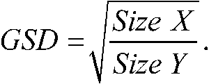
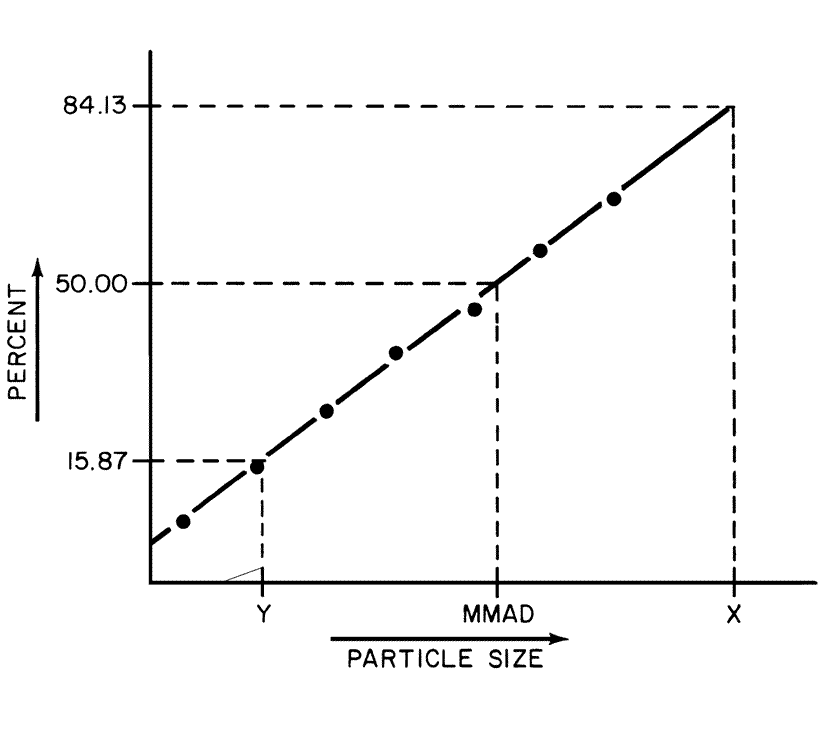
If necessary,and where appropriate,plot the percentage of mass less than the stated aerodynamic diameters,versus the aerodynamic diameter,D50,Q,on log probability paper.Calculate the GSDby the equation:
;)
Use these data and/or plot to determine values for MMADand GSDetc.,as appropriate and when necessary (see Figure 10).
;)
Fig.10.Plot of cumulative percentage of mass less than the stated aerodynamic diameter versus aerodynamic diameter.